Counter bit flip using binary flops circuit output q3 q1 q2 q0 collected would final 16. the 4 bit synchronous up counter circuit constructed with t 4 bit up down counter truth table
Circuit Design of a 4-bit Binary Counter Using D Flip-flops – VLSIFacts
Counter circuit 555 timer binary diagram circuits wiring electronic diagrams switch based schematic projects ic using wire center gates gate Counter synchronous bit diagram circuit electronics Circuit design of a 4-bit binary counter using d flip-flops – vlsifacts
Synchronous flops constructed
State flop binary circuit flops truth constructBit asynchronous counter down diagram circuit draw flip using jk binary flops ff Bit 4bit countersCircuit diagram of 3-bit synchronous counter.
Counter bit ripple circuit electronics circuits simulator simulationVhdl coding tips and tricks: example : 4 bit ring counter with testbench Circuit design of a 4-bit binary counter using d flip-flopsDiagram counter down bit block circuit precautions.

Draw a circuit diagram for 3-bit asynchronous binary down counter using
Ring counter bit verilog code vhdl diagram example tips testbench ckt tricks coding writtenBinary counter circuit diagram using ic 555 timer 4-bit ripple counter.
.


16. The 4 bit synchronous up counter circuit constructed with T

Binary Counter Circuit Diagram using IC 555 Timer

Draw a circuit diagram for 3-bit asynchronous binary down counter using
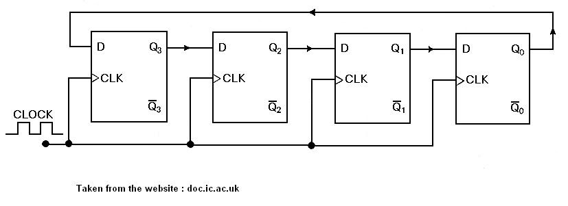
VHDL coding tips and tricks: Example : 4 bit Ring Counter with testbench

4-Bit Ripple Counter - Circuit Simulator

DeldSim - 4-Bit Down Counter

circuit diagram of 3-bit synchronous counter - Electronics Coach

Circuit Design of a 4-bit Binary Counter Using D Flip-flops – VLSIFacts